|
|
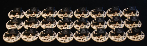
Drivere til P7 dioder. |
|
|
Skulle du trenge en driver eller en dimmer så ta kontakt. |
|
|
|
|
|
|
|
|
Dimmer til driver
|
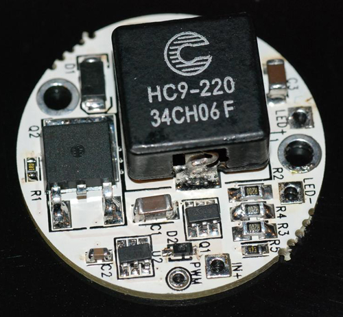
Battery input voltage can be from 2.7V to 24V (max). The FET switch (that controls power to the LED) is rated at a nominal 3.4A at 70C ambient. This means up to 3.4A of LED load can be connected to the D2Flex driver. NOTE 1: The D2Flex driver is a PWM direct drive controller. It does not regulate current or limit current, thus it is the user's responsibility to ensure the current to the LED(s) is limited externally. This may require either a series resistor or an external current regulator. NOTE 2: The user should measure the Vf of each LED at the rated current. For example, if using four P7 LEDs, measure each Vf at 2.8A and sum the total Vf (lets assume they are 3.4, 3.5, 3.3 and 3.4 for this example, so the total is 13.6V). Then take the fully charged battery voltage (typically 4 li-ion cells) of 4.2 x 4 = 16.8V. Calculate the necessary resistor as below:
|
|
|
|
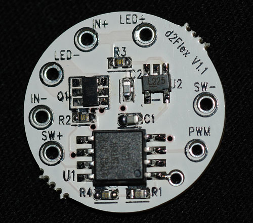
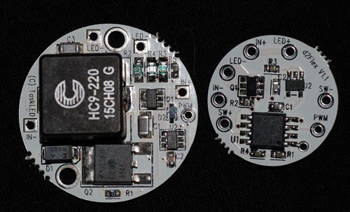
(16.8V - Total_Vf) = (16.8V - 13.6V) = 3.2V Next we calculate the necessary resistance we need to add: V = I x R, or R = V / I 3.2V / 2.8A = 1.2 ohms Without adding in the 1.2 ohm resistor in series with the P7's, the initial current when the batteries are fresh off the charge will potentially be much greater than the current rating of the FET (3.4A) and the FET can be damaged. Below is a picture of the back side of the board ( MOSI, MISO and RST pads/holes must be left unconnected, they are used during board manufacture to program/configure the board). |
|
|
|
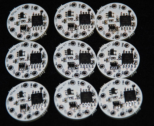
Bilder av driver og dimmer sammen. |
|
|
|
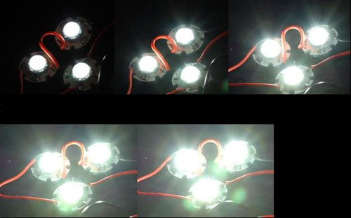
Her ser du P7 dioder dimmet i 5 nivåer. Bildene er tatt med like nnstillinger på fotoapparatet, og indikerer forskjellen i lysstyrke. |